Analytical cam design transforms the law of motion into geometry. The question stops being just which displacement is desired and starts to include: which base radius is needed, what the pressure angle will be and whether the resulting profile is physically manufacturable.
Flat-faced follower
In a cam with a flat-faced follower, contact occurs on a flat surface of the follower. The geometry can be constructed based on the prescribed displacement, but it is necessary to ensure that the profile does not generate cusps and that the follower width is sufficient to maintain contact throughout the cycle.
When base radius is small in relation to the stroke and variation of the curve, cam may develop sharp regions. These regions are undesirable because they make manufacturing difficult, concentrate stress and impair contact.
Roller follower
In the roller follower, it is customary to work first with the pitch curve, which represents the path of the roller center. The real profile of the cam is obtained by offsetting this curve by the roller radius. This improves contact, but adds the restriction that the roller radius cannot be chosen without checking for curvature.
If the roller is too large for the local curvature of the pitch curve, the profile may suffer interference or generate unfeasible contours. Therefore, the choice of \(R_r\) depends on the law of motion and the primitive radius, not just component availability.
Pressure angle
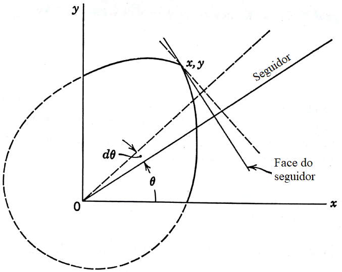
The pressure angle measures the deviation between the direction of force transmission and the desired direction of movement of the follower. High values increase lateral components, friction, loading on guides and risk of poor operation. In many teaching projects, it is used as a reference to keep the maximum angle below around 30 degrees.
The expression shows two general ways to reduce the angle: increase dimensions such as base radius or change displacement curve to reduce peaks of \(dS/d\theta\). The eccentricity \(e\) can also be used as a design feature, but it needs to be evaluated in both directions of movement.
Base radius
Increasing the base radius tends to reduce the pressure angle and smooth the profile, but increases the size of the mechanism. Decreasing the radius compacts the cam, but can generate high pressure and unfavorable curvature. The design is therefore, a compromise between space, contact, forces and manufacturing.
Curvature and cusp risk
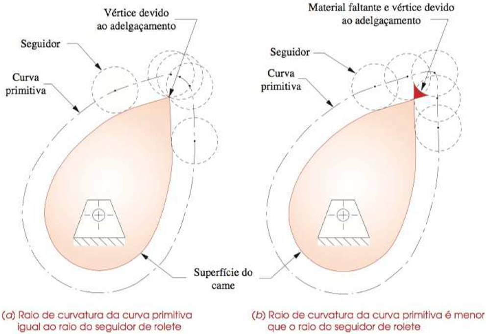
The curvature indicates how quickly the direction of the curve changes. In regions of severe curvature, the profile may become sharp or incompatible with the roller. Checking minimum radius of curvature is an essential step after choosing \(S(\theta)\), \(R_0\) and \(R_r\).
For the roller follower, the central idea is to compare the curvature of the pitch curve with the radius of the roller. If the actual surface of the cam requires a curvature smaller than that allowed by the roller, there will be a geometric problem.
Verification sequence
- define the cycle and displacement curve by sections;
- calculate displacement and relevant derivatives;
- choose an initial base radius or initial primitive radius;
- evaluate the maximum pressure angle;
- check curvature and cusp risk;
- adjust radius, roller, eccentricity or law of motion if necessary.
Analytical design does not replace mechanical judgment. It organizes the checks so that the final shape of the cam is a consequence of measurable requirements, not just a visually drawn curve.