Cylindrical spur gears are the most common introductory example, but represent only one family. When the machine layout requires another position of the axes or another contact characteristic, bevel gears, helicals and worm assemblies appear.
Bevel gears
Bevel gears transmit movement between intersecting axes, that is, axes whose lines meet at one point. The most remembered case is the change of direction by 90 degrees, but the principle is not limited to that angle. The pitch geometry stops being cylindrical and becomes conical.
In kinematic analysis, the speed ratio still depends on the equivalent geometry and teeth, but the spatial interpretation becomes more demanding. It is necessary to observe the angle between axes and the direction of rotation seen from a defined perspective. Without this reference, phrases like "clockwise" and "counterclockwise" can become ambiguous.
Helical gears
Helical gears have teeth inclined to the axis. This inclination makes contact more gradual than with straight teeth, which can reduce noise and improve smoothness. In contrast, the helix introduces axial force components, requiring appropriate bearings and supports.
When two helicals work on parallel axes, the helix angles usually have opposite signs. For crossed axes, the reading changes. Therefore, the helix angle is not just a geometric annotation: it participates in the compatibility of the gearing and the direction of the forces.
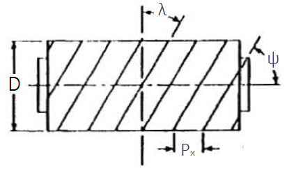
Worm and worm wheel
A worm and worm-wheel set is used when a large reduction is required in a compact space, usually between nonparallel, nonintersecting shafts. The worm has one or more starts, and the worm wheel has compatible teeth. The ideal relationship can be read in simplified form as:
A single-start worm driving a 40-tooth worm wheel, for example, produces high reduction in a single stage. The advantage is clear; the disadvantage is that contact involves significant sliding, which requires attention to efficiency, heating, material and lubrication.
Direction of rotation and viewpoint
In gears with non-parallel axes, the direction of rotation needs to be described carefully. At one view, the output may appear clockwise; in another, the same rotation appears counterclockwise. The solution is to declare the perspective or use angular velocity vectors.
This care also appears in teaching examples with bevel gears and worm. Without a perspective, the numerical result may be correct, but the direction indication is poorly defined.
Choice criteria
- Use bevel gears when the axes are concurrent and there is a need to change the direction of movement.
- Use helicals when smoothness, noise and load capacity justify additional axial force.
- Use worm gears when the priority is high compact reduction, accepting lower performance and greater lubrication requirements.
The best choice depends less on the name of the gear and more on the spatial arrangement, load, rotation, expected efficiency and acceptable maintenance.