Gears are elements used to transmit power and impose a kinematic relationship between axles. The same part that reduces speed can increase torque, change the direction of movement or serve as part of a more complex architecture, such as a gearbox or a planetary gear train.
Mechanical function
In an ideal transmission, the mechanical power entering the gear pair is approximately the power output. As rotating power is the product between torque and angular velocity, the reduction in speed is accompanied by an increase in torque, discounting losses due to friction, deformation, lubrication and contact.
This simple expression helps avoid an incomplete interpretation: the gear does not "create" power. It trades speed for torque within the limitations of the system. Therefore, gear ratio needs to be read together with effort, allowable rotation, shaft assembly and final application.
Tooth profile
The most common profile in cylindrical gears is the involute, also called involute. Its use is widespread because it allows movement to be transmitted with a practically constant speed ratio even when there are small variations in the distance between centers. This is essential in real machines, where assembly, wear and fabrication are never perfectly ideal.
Cycloidal profiles also appear in specific applications, especially when the interest is in precision and low load, as in some watchmaking mechanisms. In industrial machines, however, the robustness and standardization of the involute profile make its presence dominant.
Tooth count, pitch diameter and module
Three quantities appear all the time: tooth count \(N\), pitch diameter \(D\) and module \(m\). The pitch diameter is not the outer edge of the gear; it represents the theoretical circumference used to describe the transmission of motion. The module relates this dimension to the number of teeth:
Two gears only mesh correctly when they have compatible teeth. In practice, this means respecting module, pressure angle, face width and other manufacturing parameters. The \(D/N\) relationship is useful because it shows that it is not enough to choose teeth at random: by increasing the tooth count while maintaining the same modulus, the pitch diameter also increases.

External, internal and rack gear
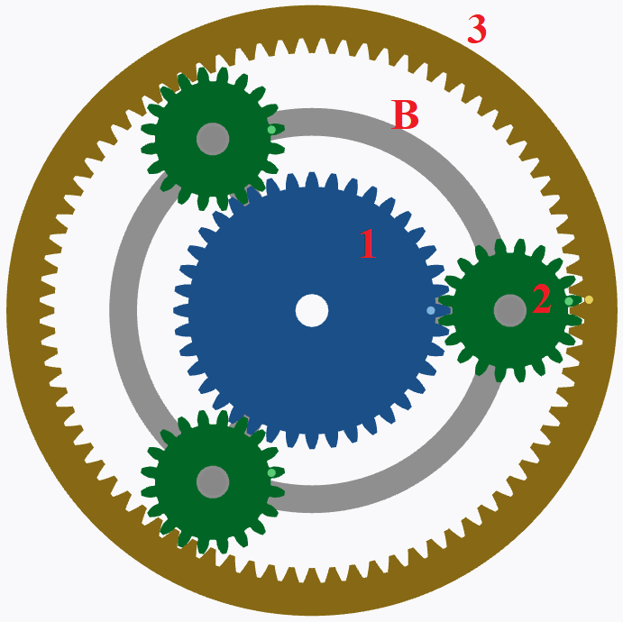
On a typical external gear, the teeth face outward. When two external gears mesh, their rotation directions are opposite. In ring gear, the teeth face inward; in this case, an external gear that meshes with it rotates in the same direction. This difference in direction becomes important when analyzing trains with multiple pairs.
The rack can be understood as a gear with infinite radius. It transforms rotation into translation and appears in directions, guides, actuators and mechanisms in which the interest is to convert angular movement into linear displacement.
Why nomenclature matters
Most errors in gear exercises do not arise from algebra, but from poor initial reading. Confusing outer diameter with pitch diameter, forgetting an intermediate gear or treating coupled gears as independent changes the entire result.
Therefore, before calculating a gear ratio, it is worth recording the topology of the mechanism. Who triggers who? Is the pair external or internal? Is there a common axis? Is there a rack? Are any elements stuck? These questions form the bridge between the geometry of the drawing and the equation that will be used.