In this article
This example presents the use of CrucibleCam to design a disk cam with a flat-faced follower. The objective is to obtain a total rise of 60 mm containing a constant-velocity interval and then apply the discontinuity-correction function so that the velocity and acceleration transitions become kinematically compatible.
Motion specification
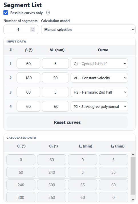
The cam must produce a total follower rise of 60 mm. Because a significant part of the stroke must occur at constant velocity, the cycle is divided into four segments: a progressive 5 mm entry, a main 50 mm constant-velocity rise, a final 5 mm transition and a 60 mm return to the initial position.
| Segment | β | ΔL | Selected curve |
|---|---|---|---|
| 1 | 60° | 5 mm | C1 — cycloidal first half |
| 2 | 180° | 50 mm | VC — constant velocity |
| 3 | 60° | 5 mm | H2 — harmonic second half |
| 4 | 60° | −60 mm | P2 — eighth-degree polynomial |
The selected curve sequence is therefore C1 – VC – H2 – P2. Cumulative displacement progresses from 0 to 5 mm, then to 55 mm, reaches 60 mm and finally returns to zero. On the manual-selection screen, the segment angles β and displacements ΔL are entered directly by the user, together with the motion law selected for each interval.
Displacement chart and initial geometry
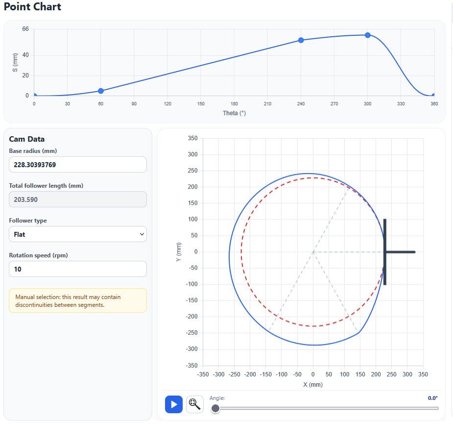
After the data are entered, CrucibleCam generates the displacement chart over the complete 360° cycle and constructs the corresponding profile. For this configuration, the program reports a minimum base radius of 228.304 mm to avoid a pointed cam profile. The example proceeds with a flat-faced follower, allowing the prescribed motion law to be related directly to the calculated cam surface.
Diagnosing the discontinuities
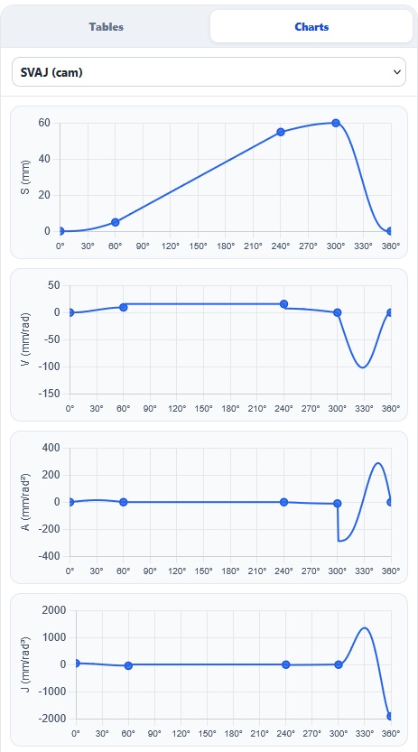
Although the total displacement and the constant-velocity interval have been obtained, the initial design has an important problem: there are discontinuities in the velocity and acceleration curves with respect to cam rotation. The jumps occur at segment boundaries because each law has its own derivative conditions and the initially assigned angular intervals do not make those conditions compatible.
Correcting these transitions is one of the most demanding parts of analytical cam design. Selecting individually suitable curves is not sufficient: the parameters that scale their derivatives must be adjusted while preserving the 360° cycle closure and the displacement required by the process. When performed manually, this procedure requires successive formulations, checks and iterations. The speed of the result depends strongly on the engineer's experience, and a prolonged adjustment can delay subsequent detailing and implementation stages.
Automatic correction by changing β
CrucibleCam introduces the Correct discontinuities function to reduce this effort. When activated, the program diagnoses the junctions and immediately presents a solution capable of making the velocity and acceleration curves compatible. This example uses the Change beta only mode, which preserves the displacements and the four selected motion laws while changing only the angular extent of the segments.
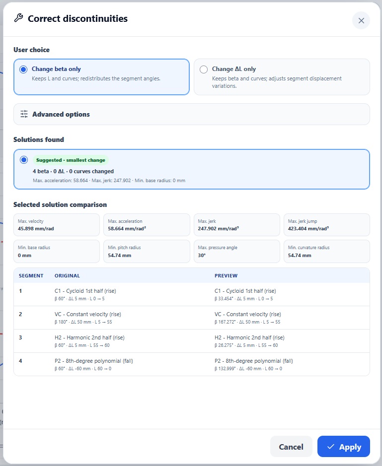
In summary, the program evaluates the velocity and acceleration conditions at the endpoints of each law and searches for β values that equalize the derivatives of adjacent segments. During the search, the intervals continue to sum to 360°, the ΔL values remain fixed, and the C1, VC, H2 and P2 curves are not replaced. The functional stroke specification is therefore preserved while the angular time available for each step is redistributed.
Corrected segments and final result
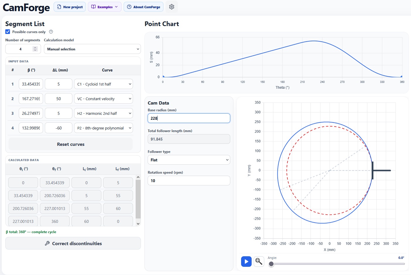
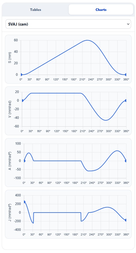
CrucibleCam calculated the following corrected intervals without changing the displacement of any segment:
| Segment | Original β | Corrected β | Preserved ΔL |
|---|---|---|---|
| 1 | 60° | 33.45° | 5 mm |
| 2 | 180° | 167.27° | 50 mm |
| 3 | 60° | 26.28° | 5 mm |
| 4 | 60° | 133.00° | −60 mm |
The new values total 360° and fully preserve the displacement program. The redistribution produces a smoother cam surface and more regular kinematic operation, with less tendency toward impacts and unwanted excitation at segment transitions. The profile no longer reflects incompatible junctions and better represents the continuous motion expected from a real mechanism.
Efficiency gain in the design process
This example demonstrates the substantial efficiency gain provided by CrucibleCam. With a single command, the program resolves an adjustment that would otherwise require analytical calculation, repeated trials and subsequent implementation in cam-generation software. The engineer remains responsible for defining the motion, choosing the laws and assessing geometric and dynamic criteria, but no longer needs to spend time on an iterative step that can be automated with traceability.
This combination of didactic clarity and practical application makes CrucibleCam useful both for understanding the origin of discontinuities and for accelerating preliminary studies of cams intended for industrial machines and mechanisms.
Questions about an equation or result? Send this page address and your calculation inputs to arturavelar@ufsj.edu.br. · About the author · Privacy