In this article
CrucibleCam is a new LASME tool for calculating and designing disk cams with translating followers. Although its interactive presentation makes it useful in engineering education, its main purpose is practical design: turning a prescribed motion into a cam profile, evaluating the resulting kinematics and correcting incompatibilities between consecutive motion segments.
The full program and Windows installer are available from the official CrucibleCam page. For a first experience without installation, users can also open the English web version or the Portuguese web version. This makes it possible to explore the basic workflow in a browser and then move on to the expanded desktop features.
An engineering tool for industrial cam design
A cam for industrial use must satisfy more than the required follower displacement. The chosen law affects velocity, acceleration and jerk; the profile must also be compatible with follower geometry, pressure-angle limits and curvature. These criteria influence dynamic loading, contact conditions, vibration, wear and the feasibility of manufacturing the mechanism.
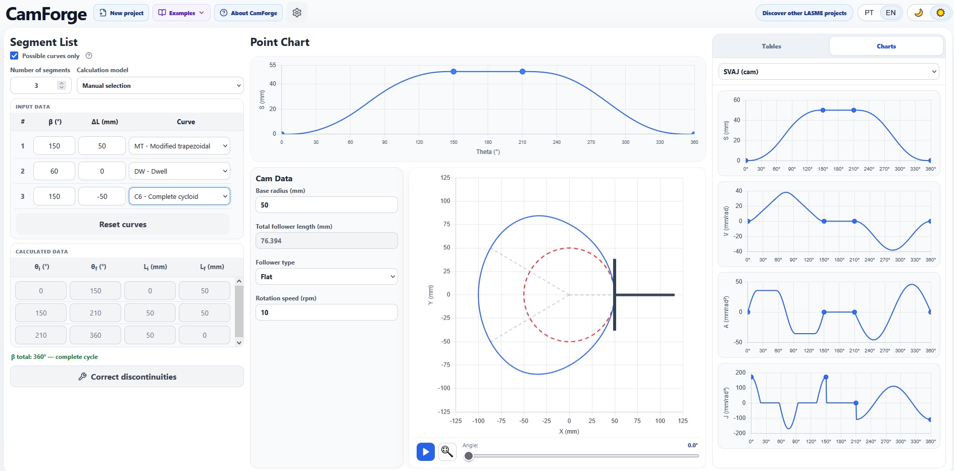
CrucibleCam organizes the complete 360° cycle into segments defined by angular extent (β) and displacement variation (ΔL). From this specification, it calculates initial and final angles and positions, generates the cam contour and presents the quantities needed for engineering assessment. The software supports flat-faced and roller followers, including roller eccentricity, and provides profile animation for visual inspection of the mechanism.
A library with 65 curve options
The reviewed version contains 65 selectable curve options, corresponding to 40 identified motion-law models when rise, return, fall and dwell variants are grouped. The library includes dwell, constant velocity, parabolic, cycloidal and harmonic laws; cubic and higher-degree polynomials; trapezoidal acceleration; double harmonic; Gutman, Freudenstein, Weber and Berzak formulations; and modified cycloidal, sinusoidal and trapezoidal curves.
This breadth is relevant because no single motion law is best for every application. A designer may prioritize lower peak acceleration, reduced jerk, compatibility with adjacent segments, smaller pressure angle or a more favorable curvature radius. CrucibleCam therefore treats curve selection as a design decision, not as a purely graphical choice.
1. Manual selection with compatible-curve filtering
In the manual selection model, the designer enters β and ΔL for each segment and chooses the motion law. When the Possible curves only filter is active, the list is reduced according to the velocity and acceleration signs required at the segment junctions. Only curves that can participate in that local transition remain visible.
This filtering substantially simplifies a task that is normally laborious. Instead of examining all 65 options at every stage, the user works with a technically relevant subset for that segment. The model preserves engineering control—because the final law is still selected manually—while reducing incompatible choices and helping the designer understand why some curves connect and others do not.
2. Automatic search for possible solutions
In the automatic search model, the input is reduced to the segment angles and displacement variations. CrucibleCam calculates the cumulative positions and angles, compares the boundary signs of velocity and acceleration and enumerates all compatible motion-law sequences found for the specified cycle.
The result is not limited to one opaque recommendation. The program presents the possible solutions, identifies the curves assigned to each segment and lets the user compare and select a sequence. In the reviewed three-segment example, the same geometric specification produced hundreds of admissible combinations, illustrating how quickly the search space grows when several motion laws are considered simultaneously.
For industrial design, this mode is valuable in the exploratory phase. It allows multiple kinematically plausible arrangements to be generated before the engineer filters them using dynamic, geometric and manufacturing criteria.
3. Correction of velocity and acceleration discontinuities
The most distinctive CrucibleCam feature is its discontinuity correction mode. Piecewise cam design is a recurrent bottleneck: each segment may be valid in isolation and still connect poorly to the next one. A velocity discontinuity implies an impulsive acceleration demand, while an acceleration discontinuity creates a jump in jerk and intensifies dynamic excitation. In a real machine, these incompatibilities may appear as impact, vibration, noise, loss of contact and accelerated wear.
Correcting these junctions manually is difficult because the normalized derivatives of a motion law are scaled by both the angular interval and the lift. A change in β alters the time available for motion; a change in ΔL alters the displacement scale. The variables are also constrained by the total cam cycle and by the process that the follower must perform.
CrucibleCam addresses this bottleneck through two explicit correction models:
- Change beta: keeps the displacement variations and selected curves, but redistributes the segment angular intervals so the velocity and acceleration conditions can be reconciled.
- Change L (ΔL): keeps the angular intervals and selected curves, but adjusts the segment displacement variations to obtain compatible junction conditions.
The correction window diagnoses the junctions, searches for continuous alternatives and previews the corrected design before it is applied. It also lets the user limit variations or lock selected variables by segment. Candidate solutions can be compared by maximum velocity, acceleration and jerk, jerk jump, minimum base and pitch radii, maximum pressure angle and minimum curvature radius.
Geometry, SVAJ and design checks
Once a solution has been selected, the program links the motion law to the physical cam. Results can be inspected as tables or charts, including cam contour, pitch curve, cam and follower SVAJ diagrams, pressure angle and radius of curvature. The animation synchronizes the cam position with the follower, which helps verify the relationship between the analytical curves and the actual mechanism.
| Design input or check | CrucibleCam resource |
|---|---|
| Prescribed motion | Segment definition by β, ΔL and motion law. |
| Follower configuration | Flat-faced or roller follower, with eccentricity for the roller model. |
| Kinematic response | Displacement, velocity, acceleration and jerk diagrams for cam and follower. |
| Geometric verification | Cam contour, pitch curve, pressure angle and curvature radius. |
| Segment compatibility | Manual filtering, automatic search and discontinuity correction. |
Didactic clarity with an industrial objective
CrucibleCam is didactic because it exposes the reasoning behind the calculation: the user sees the segment data, selected laws, boundary behavior, SVAJ diagrams and generated geometry in the same workspace. This makes it suitable for courses in mechanisms, machine design and mechanical systems.
Its scope, however, goes beyond demonstration. The combination of a broad curve library, systematic solution search, continuity correction and geometric checks makes the software a preliminary cam-design tool for industrial applications. It helps the engineer move from a process motion specification to a technically assessable cam profile and compare alternatives before detailed structural, tribological, tolerance and manufacturing verification.
Questions about an equation or result? Send this page address and your calculation inputs to arturavelar@ufsj.edu.br. · About the author · Privacy