In this article
This article presents a complete roadmap for using the module planetary gear set design from Engrenarium. The sequence was written so that assembly and analysis can be done only with the text and figures from the article itself.
What the module does
The module Planetary Design synthesizes simple and compound planetary systems from a functional specification. Instead of manually choosing tooth counts and testing combinations by trial and error, the user defines input, output, fixed component, desired gear ratio, and assembly constraints. The software then lists only those solutions that are geometrically compatible with these requirements.
The whole point of the feature is to separate two problems. The first is kinematic: what speed ratio the set needs to produce. The second is geometric: how to distribute planets, carriers and couplings so that the assembly is coherent and practical.
Designing a simple planetary gear set
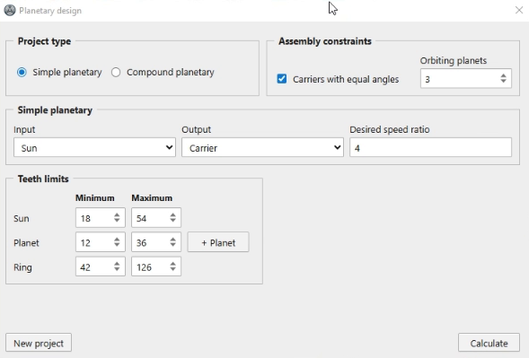
Start by opening the module and choosing the simple planetary option. To reproduce the first example, define the sun gear as the input, the carrier as the output and the ring as the fixed component. Then enter a desired speed ratio equal to \(4\).
In this case, the minimum and maximum tooth limits can now be maintained at the values filled in by the software. Run the calculation without changing these fields. The expected result is a list of solutions compatible with this specification; In the example used here, the module returns 7 results.
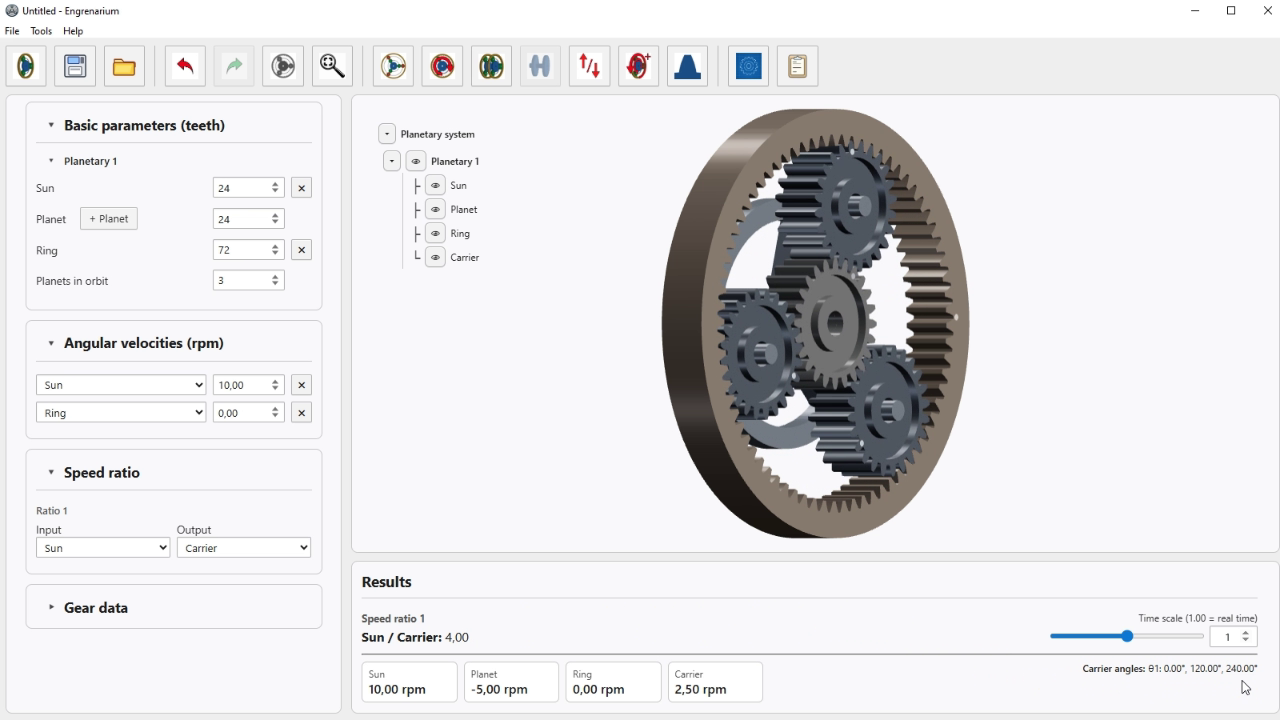
Select any of the solutions found. Engrenarium automatically assembles the corresponding planetary gear, applies the chosen tooth counts and records the design relationship. This is the first important test of the module: going from a functional specification to a complete assembled model.
- Choose Simple Planetary Gear System.
- Set sun gear as input.
- Set carrier as output.
- Set the ring gear as the fixed component.
- Enter the desired gear ratio \(i=4\).
- Keep the tooth-count limits already filled.
- Run the calculation and select one of the results.
Assembly results and constraints
When running the simple design for the first time, observe the section Assembly Constraints. The option Carriers with Equal Angles is marked, which requires uniform angular distribution of the planets. When a solution is chosen with this constraint active, the carriers appear with equal angles.
Close the assembly, open the module again, and notice that the results of the last design reappear. This allows you to switch solutions without rebuilding the entire specification. Then go back to Assembly Constraints, uncheck Carriers with Equal Angles and run the calculation again.
The expected behavior is an increase in the number of solutions. In the case used here, the total goes from 7 to 19 results. The difference is that some of these new solutions no longer respect the angular balance of the planets. Assembly remains possible, but may become less suitable from the point of view of vibration, balancing and load distribution.
In other words, the module is not just for “finding tooth counts that satisfy the geometry”. It allows you to compare solutions that are technically equivalent from a kinematic point of view, but different from a construction point of view.
Planets in series
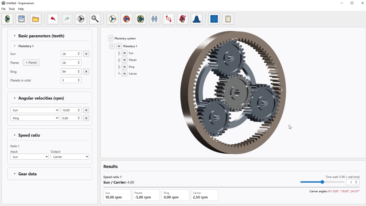
Start a new project and enable the option for planets in series for the simple planetary gear set. After calculating, choose any solution to see how Engrenarium organizes the elements. In this first test, the carrier appears straight, which is acceptable, but tends to produce a very wide ring.
Upon returning to Assembly Constraints, the option appears Straight Carrier Only. With it checked, the design is restricted to straight carriers. Uncheck this option and run the calculation again. The search space grows a lot and the number of results becomes in the thousands; In the case used here, more than 2.000 solutions appear, distributed across pages of up to 100 results.
Choose one of the new solutions. The main difference is geometric: the set becomes more compact, because the carrier is no longer straight. Even so, the spacing between planets remains at \(120^\circ\). This means that the software changes the local shape of the carrier without losing the global distribution required for assembly.
- Start a new simple design.
- Enable planets in series.
- Calculate and examine a result with straight carrier.
- Uncheck Straight Carrier Only.
- Calculate again.
- Compare ring width, carrier shape, and overall compactness.
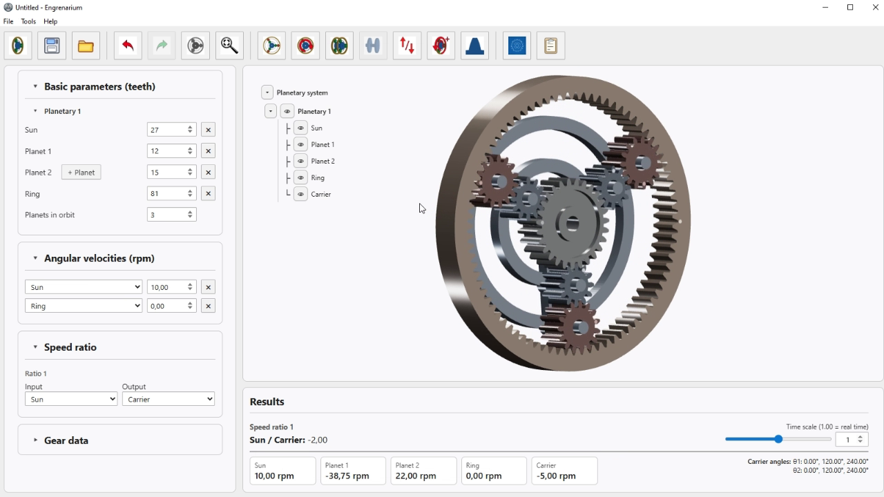
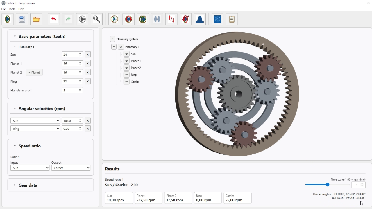
Even when carrier stops being straight, there is an important detail: the local carrier-arm angles change, but the spacing between the planets remains \(120^\circ\). In other words, the module still preserves the general distribution necessary for assembly.
Designing compound planetary gear sets
The same module also synthesizes 2- and 3-stage compound planetary gear sets. For practical use, it is worth starting with 2-stage cases, because 3-stage designs tend to generate many combinations and may require much longer calculation times.
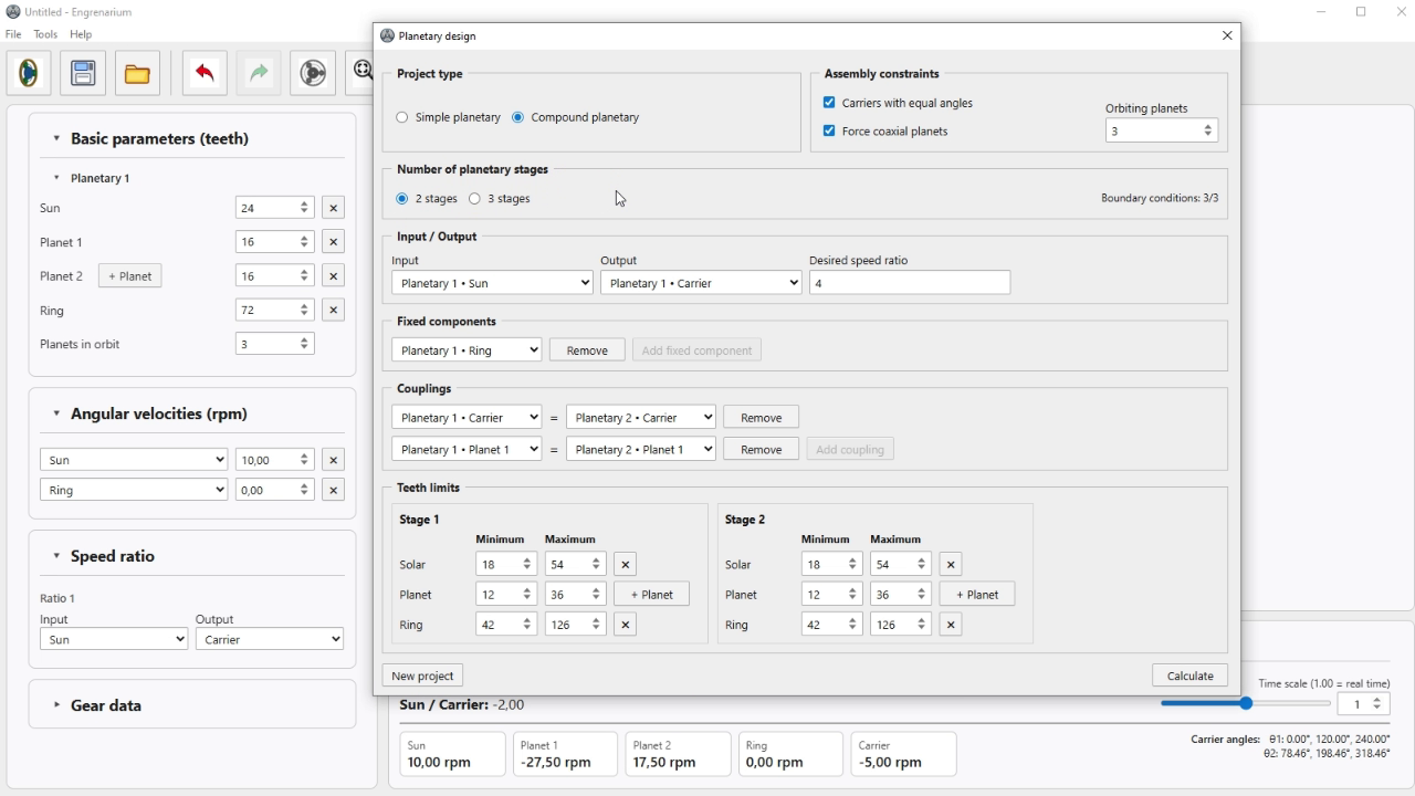
Open a new 2-stage design and keep input and output at the module's default values. In this mode, Engrenarium requires 3 boundary conditions. The input speed is automatically fixed at \(10\,\text{rpm}\), and the user needs to define one fixed component and two couplings between planetary systems. These couplings can be modified according to the desired arrangement.
| Design type | Required input data |
|---|---|
| Simple planetary | Input, output, fixed component, desired ratio and tooth limits. |
| Simple planetary gear set with planet gears in series | Same flow as before, with additional restrictions for carrier geometry. |
| 2-stage Compound planetary gear set | Automatic input speed of \(10\,\text{rpm}\), 1 fixed component and 2 inter-stage couplings. |
Forced coaxial planets
In the composite project an additional constraint called Force Coaxial Planets. When this option is active, the software adjusts the planetary modules, or the diametral pitches, so that the distance between the center of the system and the axes of the planets is the same in all stages.
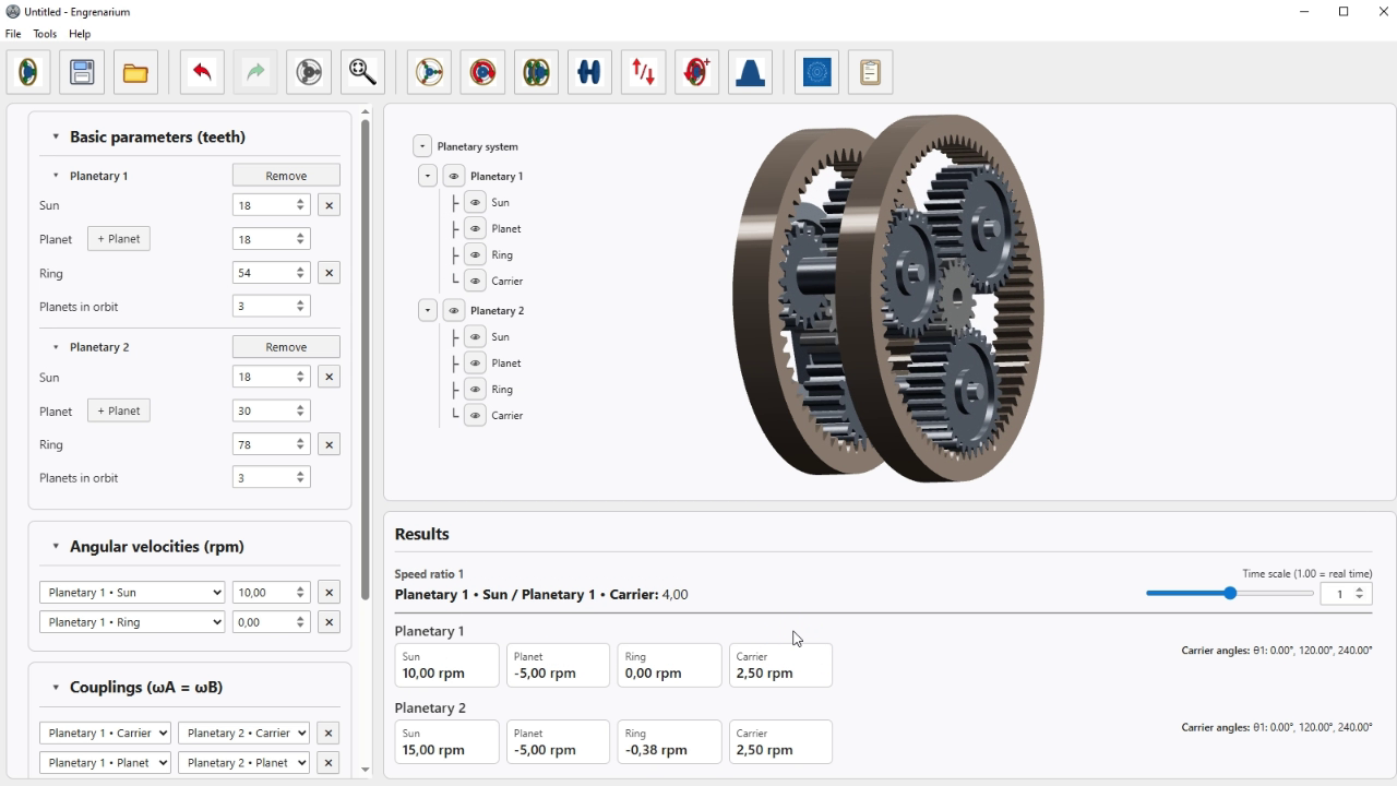
The practical result is that planets of different stages can be physically coupled and rendered as a single piece, even when their tooth counts are not the same. This restriction does not change the kinematic objective of the design; it acts on the geometric compatibility necessary for a coherent coaxial assembly.
After calculating the composite case, choose one of the solutions and check two things. First, notice visually whether the planets appear coupled together as a single set. Second, open the gear data and check if the module of any stage has been adjusted to enable this coaxiality. In the example used here, the first stage is modified to satisfy this condition.
How to use the resource judiciously
Correct use of the module follows simple logic. First, the desired kinematic behavior is defined. Then, the assembly restrictions are observed to decide which result is most suitable from a geometric point of view. The best solution is not always the first on the list, nor the one with the most apparent symmetry; it is the one that reconciles correct gear ratio, coherent assembly and practicable geometry.
Therefore, the safest procedure is to treat the module as a comparison tool, not just as an automatic generator of a single answer.
- First define the desired kinematic behavior: input, output, fixed component and gear ratio.
- Run the calculation and observe how many results meet this specification.
- Enable or disable assembly constraints to compare assembly symmetry, width, and compactness.
- In composite cases, check whether forced coaxiality changed modules or proportions between stages.
- Choose the final result based on both the gear ratio and the geometric quality of the assembly.
Questions about an equation or result? Send this page address and your calculation inputs to arturavelar@ufsj.edu.br. · About the author · Privacy