In this article
This article shows how to build a teaching model of the Allison 1000 transmission in Engrenarium and how to interpret its gear ratios. The focus is to organize the three planetary gear sets, apply the correct constraints and verify the six resulting gear ratios.
Transmission context
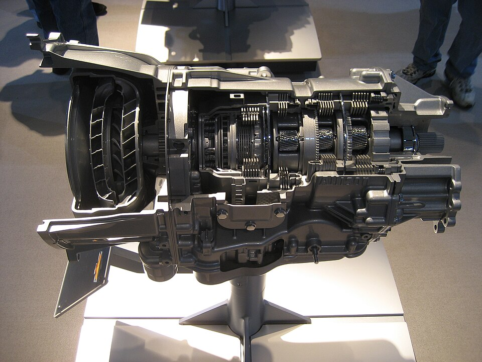
The Allison 1000 automatic transmission, manufactured by Allison Transmission, is associated with larger road vehicles, such as trucks, utility vehicles and service vehicles. The assembly is interesting to study because it uses a series-connected planetary architecture, rather than treating each gear as an isolated pair of gears.
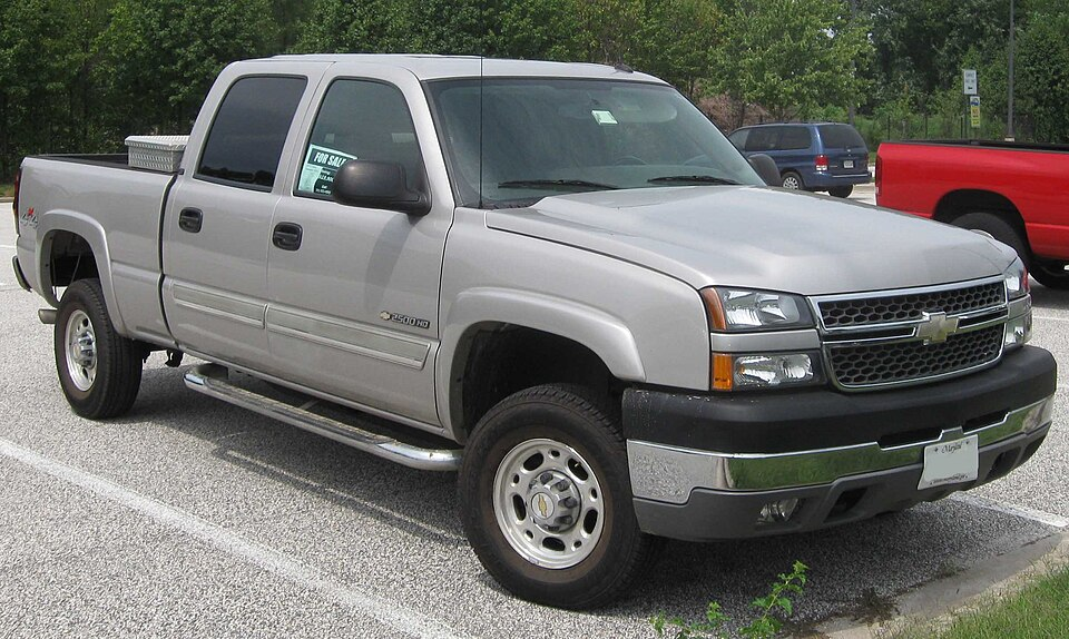
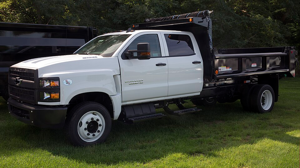
Among the vehicles mentioned in the project material are Chevrolet Silverado, Chevrolet Kodiak/GMC Topkick, GMC Sierra, Hummer H1 and Chevrolet B-Series.

Architecture at Engrenarium
The model uses three consecutive planetary systems. The planet carrier of one stage is permanently connected to the ring gear of the next stage, except in the last set, where the planet carrier is connected to the output shaft.
| Permanent connection | Function in assembly |
|---|---|
| Planet carrier 1 connected to ring 2 | Transmits movement from the first stage to the second. |
| Planet carrier 2 connected to ring 3 | Transmits movement from the second stage to the third. |
| Planet carrier 3 connected to output | Defines the model's output angular velocity. |
With this convention, the general relationship is written as the ratio of the input velocity in the first sun gear to the output velocity in the third planet carrier:
Engrenarium setup data
For assembly, the three planetary systems use the tooth counts below. This data geometrically closes each set by the relation \(N_{ring}=N_{sun}+2N_{planet}\).
| Set | Sun gear | Planet | Ring gear |
|---|---|---|---|
| Planetary 1 | \(N_{sun}=61\) | \(N_{planet}=25\) | \(N_{ring}=111\) |
| Planetary 2 | \(N_{sun}=57\) | \(N_{planet}=27\) | \(N_{ring}=111\) |
| Planetary 3 | \(N_{sun}=49\) | \(N_{planet}=27\) | \(N_{ring}=103\) |
The first step in Engrenarium is to create the three sets with these teeth. Then make the permanent connections between planet carrier and ring gear and use the first sun gear as model input.
Gear ratios
The model works with six gears: five forward gears and one reverse gear. Ratios greater than \(1\) indicate reduction; fourth gear is direct; the fifth is overdrive; and the negative sign of the reverse indicates a reversal of direction.
| Condition | Gear ratio |
|---|---|
| 1st gear | \(3.10\) |
| 2nd gear | \(1.81\) |
| 3rd gear | \(1.41\) |
| 4th gear | \(1.00\) |
| 5th gear | \(0.71\) |
| Reverse gear | \(-4.49\) |
Gear configurations
After geometry, each gear is obtained by a configuration of constraints. In Engrenarium, the practical way is to maintain the basic assembly and activate the locks or couplings below for each case.
| Gear | Ratio | Constraints to apply |
|---|---|---|
| 1st | \(i_1=3.10\) | \(\omega_{sun\,1}=\omega_{sun\,2}\) and \(\omega_{ring\,3}=0\) |
| 2nd | \(i_2=1.81\) | \(\omega_{sun\,1}=\omega_{sun\,2}\) and \(\omega_{ring\,2}=0\) |
| 3rd | \(i_3=1.41\) | \(\omega_{sun\,1}=\omega_{sun\,2}\) and \(\omega_{ring\,1}=0\) |
| 4th | \(i_4=1.00\) | \(\omega_{sun\,1}=\omega_{sun\,2}\) and \(\omega_{sun\,1}=\omega_{carrier\,2}\) |
| 5th | \(i_5=0.71\) | \(\omega_{sun\,1}=\omega_{carrier\,2}\) and \(\omega_{ring\,1}=0\) |
| Reverse | \(i_R=-4.49\) | \(\omega_{ring\,1}=0\) and \(\omega_{ring\,3}=0\) |
First, second and third gears are successively smaller reductions. Fourth gear locks the assembly in a direct condition, while fifth uses a combination of coupling and locking to produce overdrive. In reverse, two ring locks change the kinematic path and reverse the direction of the output.
Didactic reading
The Allison 1000 is a good example for studying automatic transmissions because it shows how several gear ratios can arise from the same planetary architecture. The tooth count defines the geometry; permanent connections define the structure; and the constraints for each gear define the kinematic behavior.
When checking the assembly, follow this order:
- create the three planetary gear sets with the indicated tooth counts;
- connect planet carrier 1 to ring 2 and planet carrier 2 to ring 3;
- use the first sun gear as input and the third planet carrier as output;
- apply one row of the constraint table for each gear;
- check whether the calculated gear ratio corresponds to the expected value.
Questions about an equation or result? Send this page address and your calculation inputs to arturavelar@ufsj.edu.br. · About the author · Privacy